SABRE for
sign bridges

Abstract: Sign Bridge Analysis and Evaluation System runs on windows platform personal computers and includes preprocessor, analysis, and postprocessor modules. The preprocessor includes data entry/editing, mesh generation, and on-screen graphing, among other functions. The analysis module uses the general stiffness method to perform static analysis of space frames and includes automatic load calculation (dead, wind, and ice), stress analysis, and code checking. The analysis is based upon the 2001 AASHTO “Standard Specifications for Structural Supports for Highway Signs, Luminaires and Traffic Signals”, 4th Edition, for both steel and aluminum structures, for comparison purposes, the AASHTO 3rd Edition is also available for steel structures only. New allowable stress, combined stress ratio (CSR) and especially the fatigue check are implemented in the new version. The post processor includes on-screen graphing, review of analysis results, and design of base plates and splice plates. The American Association of State Highway and Transportation Officials (AASHTO) has developed the “Standard Specifications for Structural Supports for Highway Signs, Luminaires and Traffic Signals” to govern the design of sign structures. 

 These specifications, Reference 1, standardize the requirements for load application, methods of analysis, allowable stresses and design details for sign supports and, as a result, have made easier the design and erection of sign supports. All of the entry and editing of data is accomplished with the aid of windows input screens. This relieves the user of the responsibility of creating and maintaining the formatted text files required for analysis. Each screen is divided into a number of data cells which can be edited individually. The user can move freely from screen to screen and from cell to cell and can concentrate on the meaning of the data rather than whether it is entered into the proper location. Also, a number of utilities are provided to aid in the review and editing of the data, such as on-screen graphics and output file viewing. The mesh generation capabilities cover thirty of the most common sign bridge configurations used in most of the states. This frees the user from the task of calculating and typing each structure joint and member into a data file. That data can now be generated automatically. Also, the structure solved by the stiffness method can be code-checked automatically.

Sign Bridge Components — A sign bridge is constructed of the following components, which together define the structure: 1. Sign bridge configuration — Five configurations are available in the program;

Tower types — Two types of towers are allowed, single post or double post. The tower post can be either prismatic or linearly tapered. The double posts can be trussed or nontrussed;


Beam types — Four beam types are allowed;

 
  • Pull-Down Menu System — A Windows pull-down menu system is provided as a means of navigating about the program;
  • Data Entry and Editing — The user may move to any cell on a screen by using the mouse or enter key and move to any screen by using the pull-down menu system;
  • Automatic Joint and Member Renumbering — This eliminates the need to recalculate manually and enter the other joints and/or members after deleting or inserting;
  • Section Lookup — The user may call up this file onto the screen, review the data within it, and select a suitable section;
  • On-Screen Help — Pressing “Help” displays a window on the screen with information relevant to the current program level;
  • Automatic Mesh Generation — When used, the mesh generator can create all data required to define the joints and members of a sign bridge;
  • On-Screen Graphics — The graphic image consists of a wire frame representation of the structure and can be of the current structure being edited or a structure previously analyzed;
  • Structural Analysis Capabilities — The SABRE program can analyze support structures for a wide variety of configurations, boundary conditions, member types, and loading conditions.
  • Sign Bridge types — The four beam types and two tower types can be combined in six different ways;
  • Member types — The program includes four different member types;
  • Section types — In all, eight section types are recognized, four tubular shapes and four general shapes;
  • Sign types — Rectangular signs only;
  • Walkway types — Rectangular walkways mounted parallel to the bridge beams;
  • Vertical attachment member (VAM) types — Prismatic general shapes only.

TRAP for
truss bridges

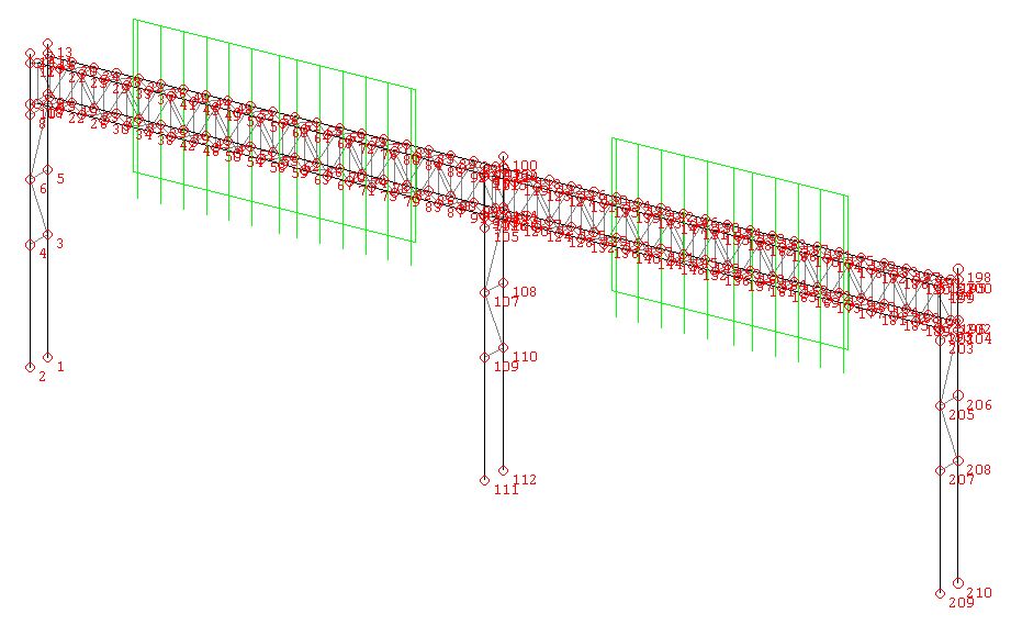
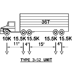
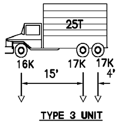
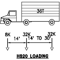
Abstract: The computer program TRAP will perform an analysis or rating group loading of a simply supported or continuous span truss having up to six spans, in accordance with the latest AASHTO specifications. Also, the program is capable of performing the analysis and rating of a prestressed truss. Live load, using State of Maryland or AASHTO, is performed automatically. In addition, a general truck configuration or rail road loading (Cooper E60, E70, and E80) having up to 40 axles may be input for a special posting rating analysis. The program uses the direct stiffness method to generate influence lines for truss member forces, cable forces, reactions, and panel point deflections. These influence lines then are used to determine the maximum compressive and tensile forces in each member under the indicated live loading. Capabilities include the automatic computation of Inventory, Operating, and Postings Ratings per AASHTO recommendations. Output contains a verification of truss geometry and loading input, and includes member, cable and panel point data, truss heights, and geometric data for all members. Also included in the output are panel point dead loads, deflections, reactions, and a force summary due to DL + LL + I for all members. Finally, a summary of the truss rating analysis output is given. Output of a group loading analysis and the governing case can be obtained by inputting the appropriate program option.

  • Load and Resistance Design (LRFD) Rating, based on the AASHTO “Guide Specifications for Strength Evaluation of Existing Steel and Concrete Bridges,” 1989 and updated Interims;
  • National Bridge Inventory (NBI) Rating, based on the AASHTO “Manual for Condition Evaluation of Bridges,” 1994 and updated Interims;
  • Load Factor (LFD) Rating, based on the AASHTO “Guide Specifications for Strength Design of Truss Bridges (Load Factor Design),” 1985 and updated Interims;
  • New Load and Resistance Factor Design (LRFD) based on the AASHTO LRFD Bridge Design Specifications, 1998 – 2000 Interim Revisions.
  1. Conforms to the latest AASHTO Specifications for design and Guide Specifications for rating, Working Stress Design (WSD), Load Factor Design (LFD), and Load and Resistance Factor Design (LRFD);
  2. Automated DL for all construction conditions including ties;
  3. Automated LL for AASHTO, Interstate, AREA, state specified and special trucks, simultaneously or separately;
  4. All impact factors are calculated automatically, either on the basis of the actual span length or loaded lengths (where appropriate);
  5. Bridge may be determinate or indeterminate and of any configuration (e.g., deck truss, through truss, etc.);

  6. Maximum positive and negative effects are given for all members and cables, reactions, and deformations;
  7. User-specified truck loadings;

  8. User can specify different levels of output;

  9. Influence line option;

  10. Combination of loads;
  11. Complete analysis of prestressed cable truss system;
  12. Complete rating for all members and all input trucks;
  13. Both English and S.I. Units allowed;

  14. WINDOWS based program including Input, Run, Graphic, Print and Help utilities.